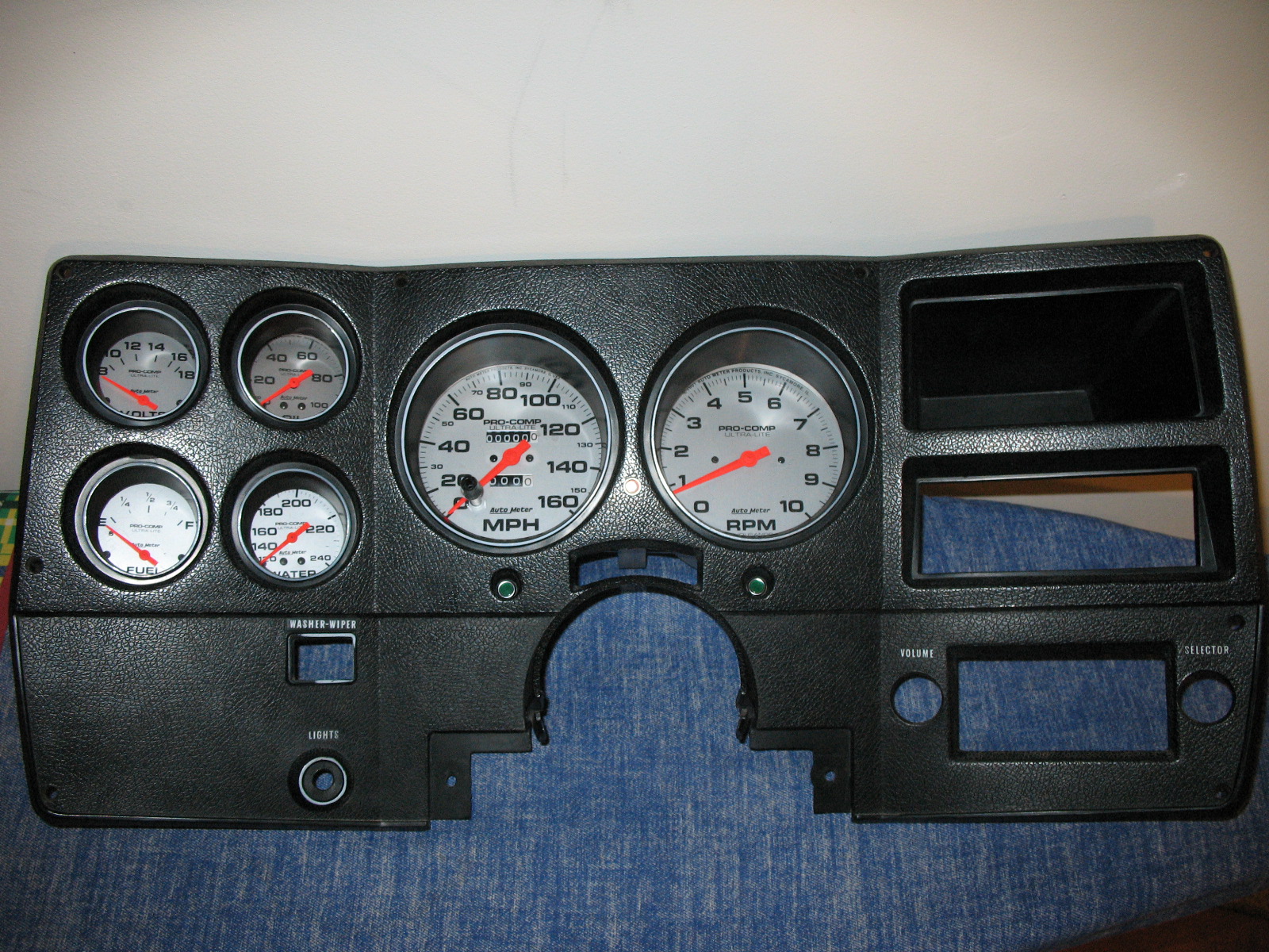
I decided to upgrade to Autometer Pro-Comp gauges. I used the 5" 160 mph Speedometer, 5" 10,000 rpm tachometer, and 2-5/8" electric oil pressure, water temp, fuel level, and voltmeter. All of these gauges are in-dash units so I had to figure out how I was going to mount them. I have seen setups with all of them mounted on the face of the bezel, and also using the billet aluminum replacement bezel that you can buy from LMC. I just didn't like the way it looked after you get them in. The gauges are tilted forward on the same plain as the bezel which makes it hard to see them. After a lot of thought I went ahead and ordered the gauges still not fully having made up my mind on what I was going to do. After I had them I started doing a little figuring. With some grinding and cutting I could mount them from behind the bezel which will look almost factory with a lot better gauges. Below is how I accomplished this. Be forewarned, this is not for the meek of heart. If you are not prepared to butcher your instrument cluster and grind on the bezel, don't start this project. I also would like to add, this is a major pain in the butt. Of all the things I have done to my truck, this has probably been one of the most aggravating. Also one other warning. If you have factory cruise control, kiss it good bye if you use the Pro-Comp mechanical Speedometer. On my 85 the pickup for the speed sensor is built into the Speedometer. The Autometer Pro-Comp mechanical Speedometer doesn't have this pickup, so no more cruise. I emailed Autometer about this. They replied and said I would need to use the Sport-Comp electrical Speedometer in order to be able to keep the cruise. I decided to keep the Pro-Comp's and get rid of the cruise. So you can see how the finished product looks, here are a few pics. Edit! Autometer now offers an electric
Pro-Comp Speedometer. This means you will be able to use Pro-Comp gauges and keep your
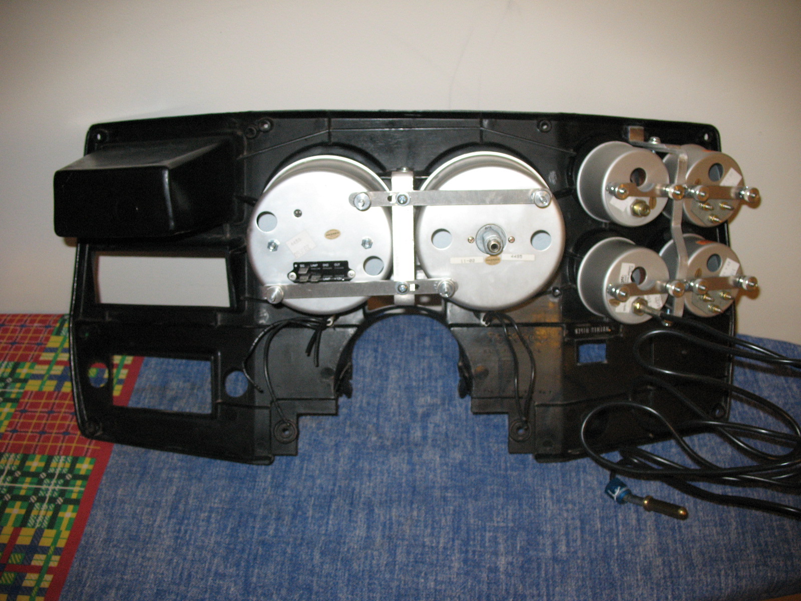
cruise control. The Start! Of course the first thing to do is remove the bezel and the instrument cluster from the dash. You will need to reach up behind the dash and remove the Speedometer cable unless yours is like mine and would slide out enough to take it loose when you pull the bezel out. Once all this stuff is out you can remove all the factory gauges. Now is when the fun starts! The only parts that you are going to reuse are the
bezel, instrument cluster and the black plastic bulb shade (for a better word). The
other pieces, gauges, glass (plastic window), and the printed circuit you don't
need. Now as I have stated, I used Autometer Pro-Comp gauges, so if you use other
manufacturers gauges, they may be a different size and you may have to use different
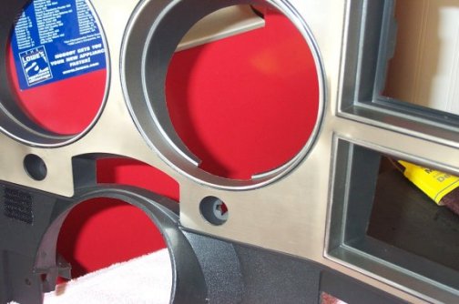
measurements. With that in mind, I am going to use the Pro-Comps as a guide. Gauge Fitting You are going to need a Dremel tool, with several different bits. On the back side of the bezel, where the hole tunnels down to the gauges, you need to cut about 1/4-inch off around the circumference of the two big holes for the Speedometer and tachometer. I took a pencil and made a mark all the way around using the edge as a guide. I used a cutoff wheel in the Dremel to cut this off. You will have to make a notch at the bottom of the hole, for the lamp holder at the bottom of the gauge. Before cutting this notch, make sure the gauge is level when viewed from the front. Use one of the small drum sanders in the Dremel to smooth the edge and make it as straight as possible. Now change to the grinding bit, sort of looks like a drill bit. You need to grind off some of the bracing between the holes so the glass on the gauges will fit up against the tunnel you just cut off. Next, with the drum sander again, grind around the outside of the tunnel about 3/8-inch down from the edge so the gauge will fit snugly up against the glass. Look from the front with the gauge put in place to make sure it fits the glass evenly. After you get both the Speedometer and tachometer fitted to their respective holes it is time to move on to the small gauges. The holes for the oil, volt, fuel, and water are a
little harder to fit. I had to remove 1/2-inch from these tunnels because they were
a lot smaller than the gauge faces. If I had just removed a 1/4-inch the tunnels
would have covered up too much of the gauge face. Go through the same process as you
did for the tachometer and Speedometer. After you have all of them shaped, make sure that they
fit and the gauge face looks right. On the two holes beside the
Speedometer you need to
take more off of the outside of the tunnel opposite the Speedometer so they will line up with
the hole better. It has to do with the angle of the tunnel I guess. After you
have all the gauges fitted to the bezel, put the drill bit in the Dremel and at the
bottom of the braces (between the holes) drill an assortment of holes down close to the
bottom of the brace. The only way I could think of to hold the gauges in place, was
to wire them in. A online friend of mine says he is
thinking of a way to make a metal plate to hold them in. I am waiting to see what he
comes up with. I am still trying to come up with a better way, but I just can't
think of one. If I figure something out I will put it on the main page so you will
know. Besides, after it is all done, you can't see these wires. Anyway,
the best advise I can give you is, take your time when fitting all the gauges. You
don't want to make a mess and end up dissatisfied with the install. Go slowly and
check the fit often. When you are completely satisfied with the fit, it is time for
mounting them to the bezel. Gauge Mounting The tachometer and Speedometer should fit real good because of the notch you have to make for the lamp holder. Also they just fit the holes better. I decided to use a little black RTV to help stick them to the bezel. Use little dabs around the outside of the hole and try to keep it back from the edges so it won't smear out onto the gauge glass when you set the gauge in place. If it still gets on the glass, wipe it off before it gets dry because it is almost impossible to get it off when dry. Let them setup about 3 or 4 hours to give the RTV time to dry, overnight would be even better. After they are dry, I used some fine single strand wire, I guess you call it picture hanging wire, to tie them down to the bezel. Put it through the hole you drilled and use a pair of pliers to twist tight. Bring it up and loop it around one of the mounting screws. Hold it tight and take the supplied nut to hold it in place. You should be able to use at least three wires each on the tachometer and Speedometer. For the small gauges, you will have to hold the gauge in
place and look from the front to get it level, so the gauge won't be tilted to one side or
the other. Once you have it set where you want it, hold it in place and use the
pencil on the back side to make two aligning marks at the edge of the gauge rim and the
edge of the tunnel. This way after you set the gauge down into the RTV you won't
need to look at the front to make sure it is where you want it. Fit all four gauges
the same way and make the pencil marks for them. You need to elevate the middle of
the bezel when the back is face up to keep it from swaying down so the gauge holes are
level. The gauges are heavy and the bezel needs this support while the RTV
dries. This will keep them from sliding around once put into place also. Now
to the RTV. You will need to use more RTV because the small gauges don't fit as
tight as the tachometer and Speedometer. Use the same care as before to keep from getting it on
the glass. Do one gauge at a time. Set it down onto the RTV and make sure it
is aligned with the mark you made, and also down against the bezel. Let each gauge
setup for a little before going to the next one so if you accidentally bump one of the
others it won't easily move out of place. After you have them all in place, let them
setup overnight. When dry, wire them down the same as the tachometer and
Speedometer. I
can't stress enough to make sure you get them where you want them before the RTV
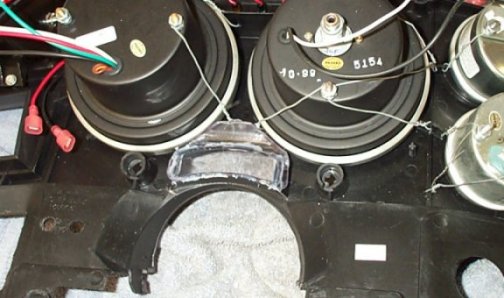
dries. It is a PITA to get them loose after it does. Cluster Cutting Take the printed circuit off the cluster. You need
to cut the back out of the cluster so will fit onto
the bezel and around the gauges and wiring. Make sure you leave the part between the
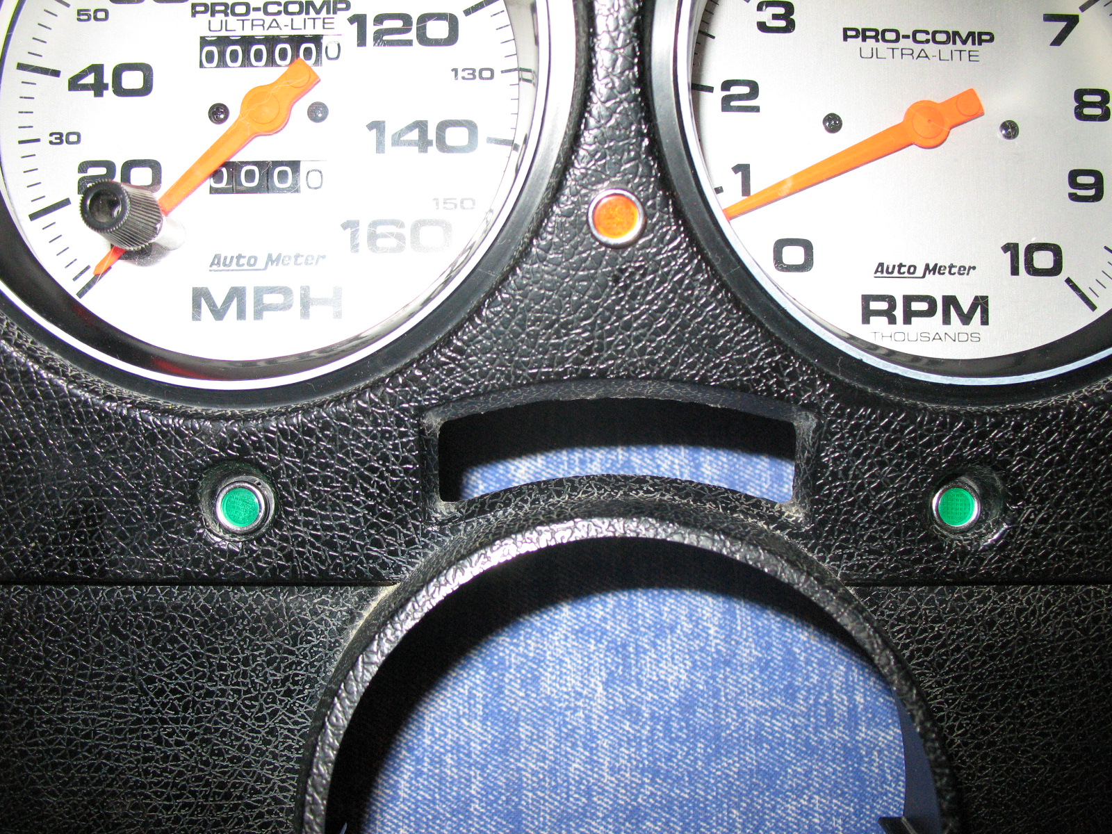
tachometer and speed because you need to use the center bulb hole to light up the shifter
dial. Cut the black background piece so you have the shifter dial covered. This is all that you need to use of the background. I
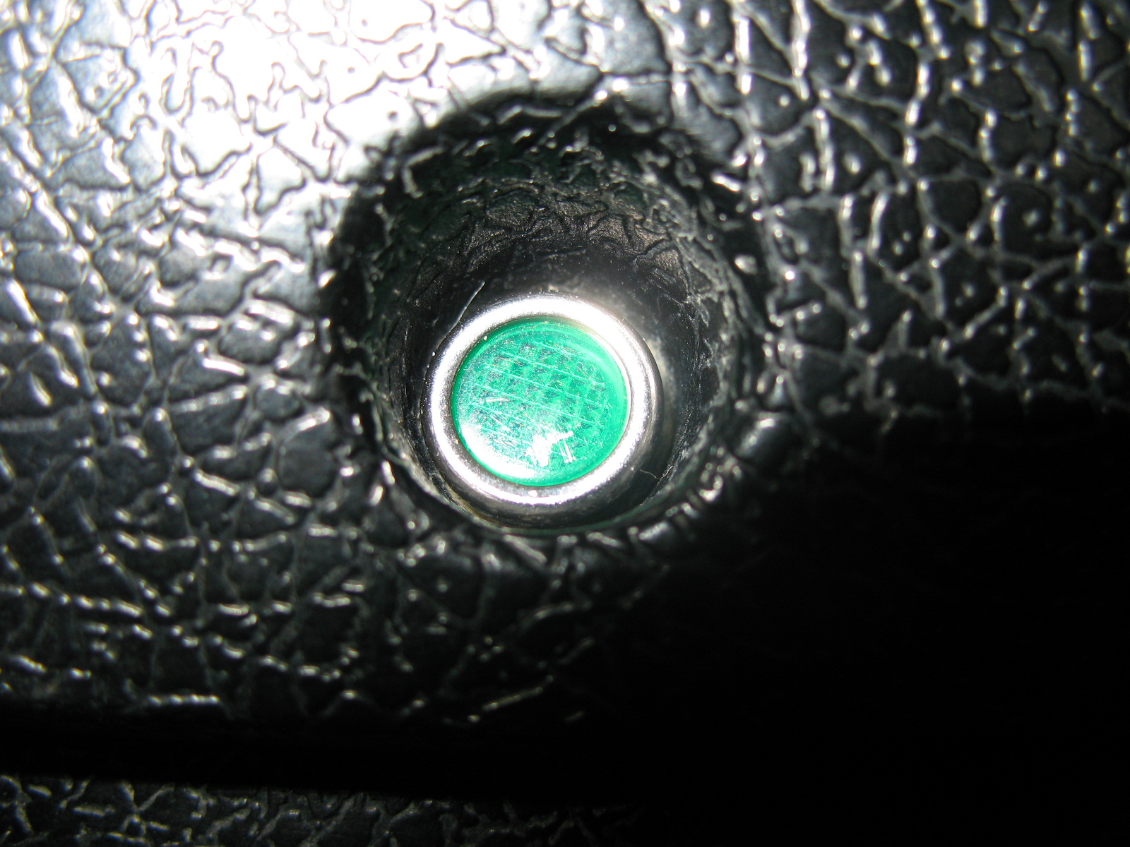
used epoxy to glue the green turn signal lenses in place. After cutting the cluster,
you don't have anything to hold them. The dull side goes to the front. You
need to use the part of the clear lens to cover
the shifter dial to help keep out dust. I cut just the part that goes over the dial
and glued it to the back of the bezel. The Wiring For the wiring, I am going to use my 85 C10 wire colors, yours may be a different color so keep this in mind. Cut all the wires from the big plug. This is what each wire is on mine. I hope this saves you some time, because it took a lot of time to figure this out. If you look at the plug you will see it has numbers on the side, at each wire. Here is what each was for on my truck. #1 Lt. green = high beam indicator lamp. #2 Gray = instrument lamps. #3 Black = ground. #4 Pink/black stripe = ignition. #5 Tan = oil pressure sending unit. #6 Pink/black stripe = ignition. #7 Pink = Fuel (will be spliced to #18 if you have dual tanks. Use the wire from #18 to hook up fuel gauge). #8 Black = ground. #9 Dk. green = water temp sending unit. #10 Black = ground. #11 Lt. blue = left turn signal indicator lamp. #12 Dk. blue = right turn signal indicator lamp. #14 Yellow = fasten seat belt light. #15 Md. blue = choke warning light. #16 Pink/black stripe = ignition. #17 Tan/white stripe (2) = park brake warning light. #18 Pink (2) = Fuel gauge sending unit (splice to other pink wire at #7). I used a Painless Performance Products universal gauge wiring harness. This makes it a lot easier to hook all the wires to the gauges. A lot of people don't want to buy the gauge harness and just wire them to each wire. This is total pain, having to put male and female spade connectors on each wire. I have been searching everywhere for some multiple pin connectors, like what comes with the Painless Performance gauge harness. Well, I finally lucked up on some. Check these out. This will really simplify things if not using a the harness. But, I still highly recommend the harness, for ease of hooking every thing up. The lamp between the Speedometer and tachometer needs to be used for lighting the shifter dial. The park brake indicator light uses the 2 tan/white stripe and pink/black stripe wires. The choke light uses the Md. blue and pink/black stripe wires. These are the only things the Painless harness won't have a plug for. Just use some male and female insulated connectors to plug these up. So I could have the high beam, park brake, and choke
indicator lights I bought 3 LED's at Radio Shack. A orange 276-272, red 276-270A,
and green 276-271A. I used the orange for the choke, green for high beam, and red
for park brake. I drilled three holes in the flat spot between the
tachometer and
Speedometer. For the turn signals and shifter dial bulbs, I reused the old bulb
holders. I just soldered some wires to the terminals that made contact with the
printed circuit. One other thing, you will need to buy a new speedometer cable
because the old won't work. You need one that screws on to the back of the
Speedometer
and the old one uses a clip to hold it on. I bought one from NAPA Auto Parts, part
number 6151603, for $15.00. This cable is as close in length to the original one as
I could find. Make sure that you tighten it securely at both ends. I thought
when I put it on the Speedometer it was tight. When I drove around the
Speedometer would
bounce between about 20 and 40 mph. I checked it and found out it wasn't. It's
hard to reach up behind the dash anyway, but make sure it is tight. Just don't over
tighten and strip the Speedometer. The End Well I guess that's about it, all I can think of right now. Now that I am done and everything is back to normal, I am glad I did it. If I had known how much work was involved would I have still done it? Yes! These gauges look real nice and work better than the old ones. As I said, this is a major job. If you don't feel comfortable tearing the dash apart, leave it the way it is. It does make a big mess until you get it back together. Update! Since installing the gauges I had problems with the electric oil pressure gauge. I got tired of messing with it and decided to install a mechanical gauge in its place. The electric gauge wouldn't read correct, replaced the sender, still no good. Autometer offered to check the gauge and repair or replace it if it was defective. I just felt I needed to be safe and go with a mechanical gauge and not have to worry if it was telling me the truth on such an important subject. Update 2! I thought I would
let everyone know that has asked me if I had found a better way of mounting the gauges
besides wire. Well no. I haven't really felt it was necessary since I haven't
had any trouble out of mine. They are still just as tight as when I first did
them. I am sure there are plenty of ways to do it and probably some which are maybe
better or at least cleaner than my way, but the wires are working just fine.
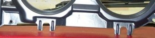
Update: By Jeff Drew As I am sure you will agree, Mike did an excellent job documenting the gauge install he did on his '85 C10. I decided to take a stab at installing Autometer Ultralight gauges in my '73 C10, and came up with what I feel is an improvement to mounting the gauges to the bezel, and thought I would add to an already great article that I feel will benefit anyone thinking about or attempting to do a similar modification. While I am at it, I will throw in a few pointers I discovered along the way to make things easier yet. Just like Mike did, the gauge openings on the back side of the bezel need to be trimmed back, opening up the diameter of the ring and allowing more gauge face visibility. I simply used a rotary tool (Dremel in my case) with simply a cut-off wheel. You can either eyeball this, or find yourself some thin masking tape and run it around the ring, then use the rotary tool and follow the tape line while cutting. Regardless of how you do this step, be prepared to spend some time sanding smooth and leveling off the back of the rings so your gauges will have a smooth surface to sit on. I found that it is VERY important to get the top smaller openings cut, sanded smooth, and leveled with each other as well as the same for the bottom smaller openings. This can easily be done with a smaller sanding block and medium to fine sandpaper. Simply sand each pair of openings together, keeping the block as flat as possible and double checking your work frequently. Similar to automotive block sanding, just on a smaller scale. I didn't feel or see the need to enlarge the two larger openings (speedometer and tachometer) and just left them alone. With the openings cut, next up was to test fit the gauges. As I mentioned above, I am installing Autometer Ultralight gauges, which are surface mounted gauges...and they did not fit well at all. In order to make these fit on the back side of my bezel, I had to tear apart the gauges and modify them slightly to get them to seat and look right. This simply entailed removing the trim ring from each gauge, which is just a very thin piece of aluminum, which pried of easily with a small screwdriver and small Vice Grips. Once the trim ring was removed, I now had to figure out what to do with the lens and lens trim ring that were no longer secured to the gauge (the trim ring held these in place by sandwiching them between itself and the gauge body). I remedied this by using a plastic & metal two part epoxy glue. I sanded the gauge housing and mating lens trim ring surface with fine sandpaper, applied a very thin coat of epoxy, and let them bond. Once the lens trim ring was adhered to the gauge, I adhered the lens to the lens trim ring, again with a very thin coat of epoxy. I should mention that the previous steps applied to the four smaller gauges, the two larger gauges were a tad easier due to their construction. For the larger gauges, I still had to pry off the ring, and figure out how to attach the lens trim ring and lens...but all I had to do was to align the lens and lens trim ring with the gauge body, run one piece of masking tape over the lens and onto the body (just to hold it in place), and run a small bead of epoxy around the edge of the gauge where it meets up with the lens...effectively adhering everything back together. Regardless of how the gauges go back together, these steps are crucial to take your time on, as the epoxy can make a mess, and potentially find its way onto the gauge face or lens. Once on, and dried, it will be impossible to get off. The following part of my gauge install is where I deviate from Mikes install quite a bit. I was never a fan of wiring the gauges in as Mike did, but figured I would give it a try because I myself couldn't come up with a better, easier way at the time. So I went and purchased some jewelry wire, and failed miserably trying to get the gauges in...straight and tight. After much debate and thought, I decided to take some measurements, and design some brackets out of aluminum, and solid mount them. with my designs on paper, I transferred them to CAD (computer aided drafting), and had them laser cut out of flat stock aluminum at a friends work. With the pieces cut and in my possession, it was simply a matter of bending up the gauge mounting brackets, attaching them to the bezel, and mounting the gauge assemblies to the brackets. As you can see, the results look just as good from the front side, but the back side I feel is a better design, and allows the gauges to be installed easier, as serviced easier should the need arise. Wrapping up my install was to add LED turn signal and high beam indicators. These were purchased from Jegs, with the part numbers being 11052 and 11063. All that was required to install these was to drill out the stock "arrow" turn signal indicators, and epoxy (or a press fit would work) the LED indicators to the bezel. The high beam I mounted between the larger gauges, by drilling a hole thru the center of a molded shaft on the back side of the bezel, that just so happened to be in a perfect spot. Anyhow, that is my contribution to Mikes article. I hope all of this will help should you decide to upgrade the gauges in your truck. Click the thumbnails below to see the full size image of the completed cluster.
|

